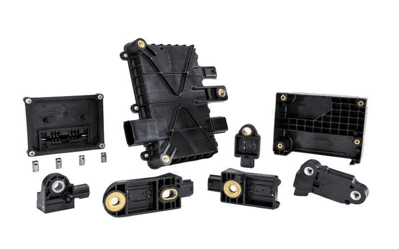
- CNC machining costs $30–$150 per part regardless of quantity, while injection molding drops to $1–$5 per part once tooling ($3,000–$100,000+) is amortized — the break-even typically falls between 500 and 1,500 units.
- CNC machining holds ±0.025 mm on critical features; injection molding achieves ±0.1–0.2 mm under standard conditions, with tighter tolerances requiring mold-flow simulation and process validation.
- Converting a CNC prototype design to injection-moldable geometry requires at least 8 DFM changes — uniform wall thickness, draft angles, gate locations, and elimination of internal sharp corners are the most commonly missed.
- A hybrid CNC-to-bridge-tooling-to-production-mold workflow lets teams validate form, fit, and function before committing $20,000+ to a hardened steel mold.
- How CNC Machining and Injection Molding Work
- The Break-Even Volume Chart
- Tolerance and Precision Comparison
- 10 Design Features That Dictate the Process
- CNC-to-Injection-Molding DFM Conversion Checklist
- Material Selection by Process
- The Hybrid Prototype-to-Production Workflow
- Surface Finish and Cosmetic Options
- When CNC Machining Wins Even at High Volume
- FAQ
Your engineering team just validated 15 CNC-machined prototypes and the design is locked. The next order is 5,000 units — do you keep machining each one, or invest in injection mold tooling? That decision hinges on four variables most comparison guides gloss over: your actual break-even volume, the tolerance degradation you can accept, the design changes required for moldability, and how quickly you need production parts in hand.
This guide provides the cost math, tolerance data, and a step-by-step DFM conversion checklist so you can make that call with numbers, not assumptions. It does not cover die casting, urethane casting (see KUSLA Prototype’s urethane casting guide), or 3D printing — each deserves its own analysis.
How CNC Machining and Injection Molding Actually Work
CNC machining removes material from a solid block using rotating cutting tools controlled by G-code, producing one finished part per cycle with no tooling investment beyond standard fixtures. Injection molding forces molten polymer into a precision-machined steel or aluminum cavity under 500–2,000+ bar pressure, cooling it into shape — the mold is the investment, and each cycle produces one or more identical parts in 15–60 seconds.
The fundamental economic difference: CNC cost scales linearly with quantity (part 1,000 costs the same as part 1), while injection molding front-loads cost into tooling and then delivers near-zero marginal cost per unit. Every decision in this guide flows from that distinction.
The Break-Even Volume Chart — When Injection Molding Starts Winning on Cost
Injection molding becomes cheaper per unit than CNC machining at a specific volume that depends on part complexity, mold cost, and CNC cycle time — for most small-to-medium plastic parts, that crossover falls between 500 and 1,500 units.
| Quantity | CNC Cost/Part | CNC Total | IM Tooling | IM Cost/Part | IM Total | Winner |
|---|---|---|---|---|---|---|
| 1 | $85 | $85 | $4,500 | $3.50 | $4,504 | CNC |
| 50 | $75 | $3,750 | $4,500 | $3.50 | $4,675 | CNC |
| 200 | $70 | $14,000 | $4,500 | $3.50 | $5,200 | IM |
| 500 | $65 | $32,500 | $4,500 | $3.40 | $6,200 | IM |
| 2,000 | $60 | $120,000 | $4,500 | $3.20 | $10,900 | IM |
| 10,000 | $55 | $550,000 | $4,500 | $2.80 | $32,500 | IM |
Basis: simple ABS enclosure, 120 × 80 × 30 mm, single-cavity aluminum mold. CNC prices reflect KUSLA Prototype’s typical quotation for 3-axis machining in ABS stock; IM prices assume amortized tooling over stated quantity. Complex geometries requiring side actions, multi-cavity molds, or tight-tolerance steel tooling shift the break-even rightward to 1,000–3,000 units.
Three Variables That Shift the Break-Even
Mold complexity is the largest cost lever. A simple open-shut mold runs $3,000–$8,000 in aluminum; add side actions, lifters, or hot runners and the price jumps to $15,000–$50,000+. Multi-cavity molds (2×, 4×, 8×) reduce per-part cost but raise the upfront investment. CNC cycle time determines the baseline you are comparing against — a 45-minute 5-axis part at $150 breaks even with injection molding far sooner than a 5-minute 3-axis part at $30. Material cost matters less than most engineers expect: ABS resin at $2–$4/kg adds only $0.15–$0.60 per small part, while CNC stock waste (buy-to-fly ratio of 5:1 to 20:1 for metals) can dominate machining cost.
Tolerance and Precision: What Each Process Actually Holds
CNC machining delivers repeatable tolerances of ±0.025 mm on critical dimensions with standard 3-axis work, tightening to ±0.005 mm with grinding or jig boring — every part is cut independently from solid stock, so there is no process drift between part 1 and part 500.
| Dimension | CNC Machining | Injection Molding (Standard) | Injection Molding (Fine) |
|---|---|---|---|
| Linear (<100 mm) | ±0.025 mm | ±0.15 mm | ±0.08 mm |
| Linear (100–300 mm) | ±0.05 mm | ±0.25 mm | ±0.12 mm |
| Hole diameter | ±0.013 mm (reamed) | ±0.08 mm | ±0.05 mm |
| Flatness (100 mm span) | 0.02 mm | 0.10–0.30 mm | 0.05 mm |
| Surface finish (Ra) | 0.4–3.2 µm | 0.1–1.6 µm (mold-dependent) | 0.05 µm (polished mold) |
| Part-to-part repeatability | Consistent (no drift) | Requires Cpk validation | Cpk ≥ 1.33 achievable |
CNC values per ISO 2768-f (fine); IM standard per ISO 20457 Class M; IM fine per Class F with mold-flow-optimized gating and controlled cooling. Sources: Machinery’s Handbook 31st Ed.; ISO 20457:2018.
Injection molding tolerances depend on material shrinkage (0.4–2.5% depending on polymer), gate location, cooling uniformity, and fiber orientation in filled resins. Warpage risk increases with non-uniform wall thickness — a wall step from 2.0 mm to 3.5 mm creates differential cooling that can pull a flat surface 0.3 mm out of plane. KUSLA Prototype runs mold-flow simulation (Moldex3D) on every tooling project to predict and compensate these effects before steel is cut.
10 Design Features That Dictate Your Process Choice
Certain part geometries make the CNC-vs-injection-molding decision for you — regardless of volume, some features are only practical in one process or the other.
| # | Design Feature | CNC | Injection Molding | Notes |
|---|---|---|---|---|
| 1 | Internal undercuts | Difficult (EDM or multi-setup) | Side actions / lifters | IM handles complex internal features with mold mechanisms |
| 2 | Uniform thin walls (<1.5 mm) | High chatter risk | Standard | IM excels at consistent thin walls; CNC risks deflection |
| 3 | Sharp internal corners | End mill radius ≥0.5 mm | Stress concentrators + sink marks | IM requires R ≥ 0.5× wall thickness |
| 4 | Threads (internal/external) | Single-point or tap | Unscrewing cores or post-mold inserts | CNC threads are cheaper unless volume justifies core pulls |
| 5 | Tight tolerances (<±0.05 mm) | Standard capability | Requires precision mold + process control | CNC is the default for CTQ features |
| 6 | Living hinges | Not feasible | PP/PE integral hinges | Material flow creates molecular alignment for flex life |
| 7 | Snap fits / clips | Possible but fragile in metals | Standard in plastics | IM enables flexible polymer snap features |
| 8 | Large flat surfaces | Fly-cut to 0.02 mm flat | Warp risk from cooling gradients | Ribs + uniform wall mitigate IM warp |
| 9 | Multi-material / overmold | Not possible | 2K / insert molding | Soft-touch grips, seals, multi-color |
| 10 | Metal parts | Al, steel, Ti, brass, copper | MIM only (limited alloys) | CNC is the primary metal process |
When a design contains features from both columns — tight-tolerance metal inserts inside a thin-wall plastic housing, for example — the answer is often both processes: CNC-machine the metal inserts and injection-mold the plastic body around them via insert molding.
Not sure whether your part should be machined or molded? Send your 3D file for a free process recommendation with cost comparison.
Upload Your DesignCNC-to-Injection-Molding DFM Conversion Checklist
Converting a CNC prototype design into an injection-moldable part requires at least 8 geometry modifications — missing any one can cause short shots, sink marks, warpage, or tooling cost overruns.
- Add draft angles: 1–2° on all vertical surfaces (3° for textured faces). CNC parts have zero draft; molds cannot eject without it.
- Uniform wall thickness: Target ±10% variation. CNC parts often have solid sections and pockets of varying depth that must become uniform shells (1.5–3.0 mm for ABS/PC).
- Radius all internal corners: Minimum R = 0.5× wall thickness. Sharp CNC-machined corners become stress concentrators and flow restrictors in injection molding.
- Add ribs instead of thick sections: Replace solid bosses with rib structures (rib thickness = 0.5–0.7× wall). Thick sections cause sink marks and extend cycle time.
- Design gate location: Identify cosmetic and structural requirements to position the gate where vestige is acceptable. CNC parts have no gate consideration.
- Add ejector pin pads: Flat surfaces for ejector contact (≥3 mm dia.). CNC parts are unclamped after machining; molded parts need ejection force distributed to avoid distortion.
- Eliminate undercuts or add side actions: Internal features that a CNC cutter reaches from multiple setups may require expensive mold side actions. Redesign to straight-pull geometry where possible.
- Specify shrinkage allowance: Mold cavity is oversized by the material’s shrink rate (ABS: 0.4–0.7%; PA66: 1.2–2.0%; PP: 1.0–2.5%). CNC cuts to final dimension directly.
- Review parting line location: Where the mold halves meet creates a witness line. Position it on non-cosmetic edges. CNC parts have no parting line.
- Validate flow path: Run mold-flow simulation to confirm fill, cooling balance, and weld line locations before cutting steel.
KUSLA Prototype provides free DFM review on every injection molding project. Engineers flag these issues with annotated 3D models before tooling begins, preventing costly mid-build mold modifications that typically add $2,000–$8,000 and 2–3 weeks.
Material Selection Matrix: Which Process Handles What
CNC machining works with virtually any machinable metal or engineering plastic in stock form, while injection molding is limited to thermoplastics (and some thermosets) that flow under heat and pressure — material choice often narrows the process decision before cost or volume enter the equation.
| Material Category | CNC Machining | Injection Molding | Typical Application |
|---|---|---|---|
| Aluminum alloys (6061, 7075) | Standard | Not applicable | Structural brackets, housings, heatsinks |
| Stainless steel (304, 316, 17-4PH) | Standard | MIM only (limited) | Medical instruments, food-contact parts |
| Titanium (Grade 5 Ti-6Al-4V) | Specialty | Not applicable | Aerospace, implants |
| ABS | Machinable | Standard | Consumer enclosures, housings |
| Polycarbonate (PC) | Machinable (stress cracking risk) | Standard | Transparent covers, lenses |
| Nylon (PA6, PA66) | Machinable | Standard (shrink management needed) | Gears, bearings, structural clips |
| PEEK | Preferred (low volumes) | Possible (high melt temp, special machine) | Aerospace, semiconductor, medical |
| PP / PE | Gummy, poor finish | Standard | Packaging, living hinges, containers |
| Silicone / LSR | Not feasible | Liquid injection molding | Seals, medical devices, overmolds |
| Brass / Copper | Excellent machinability | Not applicable | Connectors, fittings, electrodes |
For a deeper comparison of specific alloys, see KUSLA Prototype’s materials guide hub, which covers aluminum, stainless steel, titanium, brass, copper, and engineering plastics with machining-specific parameters.
The Hybrid Workflow: CNC Prototype → Bridge Tooling → Production Mold
Most successful product launches use CNC machining and injection molding sequentially — not as competing choices but as stages in a prototype-to-production pipeline that manages risk at each step.
Stage 1: CNC Prototypes (1–50 units)
CNC-machine functional prototypes in production-intent material. Test form, fit, and function. Iterate design freely — each change costs only a G-code update, not a mold modification. Timeline: 3–7 business days. Cost: $30–$150 per part depending on complexity. KUSLA Prototype typically delivers 5–15 prototype iterations before a design stabilizes.
Stage 2: Bridge Tooling (50–5,000 units)
Cut a single-cavity aluminum mold ($3,000–$8,000) for market testing, regulatory samples, or early sales. Aluminum tooling lasts 5,000–10,000 shots and can be ready in 2–3 weeks. Per-part cost drops to $3–$8. This stage validates moldability before committing to hardened steel — catching fill issues, sink marks, or warpage early saves $10,000–$30,000 in steel mold rework.
Stage 3: Production Mold (5,000+ units)
Commission a hardened P20 or H13 steel mold with the optimized geometry from Stage 2. Multi-cavity (2×, 4×, 8×) if volume justifies it. Cost: $8,000–$50,000+. Mold life: 100,000–1,000,000+ cycles. Per-part cost: $1–$5. Timeline: 4–8 weeks for tooling.
This staged approach is how KUSLA Prototype’s clients in consumer electronics and medical devices manage the transition from concept to mass production. The low-volume manufacturing service page explains how bridge tooling fits into the broader production scaling workflow.
Surface Finish and Cosmetic Options Compared
Injection molding achieves finer as-produced surface finishes than CNC machining because the part replicates the mold surface — a polished mold produces mirror-like parts (Ra 0.05 µm), while a textured mold imparts consistent VDI or SPI finishes across every unit.
| Finish Type | CNC Machining | Injection Molding |
|---|---|---|
| As-machined / as-molded Ra | 0.8–3.2 µm (tool marks visible) | 0.1–1.6 µm (mold surface replicated) |
| Mirror / optical | Secondary polishing required | SPI A-1 mold polish (Ra 0.05 µm) |
| Textured / matte | Bead blasting post-process | Mold texture (VDI 3400, MT series) — built into tooling |
| Anodizing / plating | Standard for metals | Painting / pad printing for plastics |
| Color-through | Material color only | Masterbatch colorant — no painting needed |
| Consistency across batch | Varies with tool wear, setup | Identical (mold-dependent) |
For a deeper look at surface roughness measurement and specification, see KUSLA Prototype’s Ra vs Rz guide which covers ISO 21920 parameters and their practical impact on part function.
When CNC Machining Wins — Even at High Volume
CNC machining remains the better choice even above the break-even volume when the part requires metal construction, extreme tolerances, frequent design changes, or material properties that injection molding cannot replicate.
Metal parts at any volume. Aluminum brackets, steel shafts, titanium implants, and brass connectors have no injection-molding equivalent (MIM covers only small, simple geometries in limited alloys). CNC is the production process, not just the prototype tool.
Tolerances tighter than ±0.05 mm on plastics. If a plastic part requires ±0.025 mm on critical features — common in optical assemblies, semiconductor fixtures, and medical cartridges — CNC machining from bar stock is more reliable than trying to hold those tolerances through mold shrinkage, cooling variation, and process drift.
Design instability. Products still iterating at 500+ units (common in hardware startups and medical device V&V phases) should stay CNC. A $5,000 mold modification on a $15,000 tool eats the per-part savings that justified the mold in the first place.
Mixed material assemblies. When a product combines CNC-machined metal structures with molded plastic components, the metal parts remain CNC regardless of total volume. KUSLA Prototype machines these assemblies in a single facility — metal and plastic processes run in parallel to compress lead times.
Low-volume, high-mix production. Contract manufacturers running 20+ part numbers at 200–500 units each often find CNC more economical than maintaining 20 separate molds. Setup changeover on a CNC mill takes minutes; mold changes take hours.
Frequently Asked Questions
- ISO 2768-1:1989 — General tolerances for linear and angular dimensions
- ISO 20457:2018 — Plastics, injection-moulded parts, tolerances and acceptance conditions
- Machinery’s Handbook, 31st Edition — Machining tolerances and process capabilities
- VDI 3400 / SPI surface finish classification
- KUSLA Prototype internal production data (2024–2026 quotation and tooling records)