In the process of product development and manufacturing, Engineers from different departments are involved including design engineers, process engineers, body engineers, quality engineers, measurement engineers, and more. Each engineer has an understanding of the product’s requirements and standards. In order to have smooth communication during the product development process between these departments, a unique and authoritative standard is needed for everyone. This is where GD&T comes to be a uniform standard. In this article, we will introduce everything about GD&T.
WHAT IS GD&T?
GD&T stands for Geometric Dimensioning and Tolerancing, which is a set of rules and symbols used on a drawing. Geometric tolerancing is a comprehensive notation method that is a member of the tolerance notation family. Compared to traditional linear dimension notation, it has unique advantages and is accepted by more mechanical professionals.
After CNC machining, parts will have dimension tolerances, which result in differences between the actual dimensions and dimensions specified by ideal geometric bodies. These differences in shape are known as profile tolerances, while differences in mutual position are known as positional tolerances. In short, these differences mean geometric tolerances.
WHAT IS THE PURPOSE OF GD&T?
As mentioned, the main purpose of GD&T is to deliver all dimension information from design engineers to manufacturers. the GD&T on the drawings can tell the manufacturer how the accuracy of each feature needs to be controlled. This is to make sure the final parts meet the desired function performance.
HOW DOES GD&T WORKS?
GD&T works by indicating a feature’s tolerance zone value. this zone value means the maximum and minimum of the feature dimension. with a Feature Control Frame, all the features to be controlled, tolerances, and datums are in it.
TERMS RELATED TO GD&T
Before diving into the details of GD&T, it is necessary to understand the common terms in the GD&T definition, as they are key components in explaining the system. Let us walk through these terms and understand what they stand for:
- Datum: Datum is a geometric ideal element related to the measured feature and used to define its geometric positional relationship (such as axis, straight line, plane, etc.), which can be composed of one or more features on the part.
- Datum Feature: It is a feature used to establish a datum and be contacted during the machining and inspection process; it has a sufficiently accurate actual surface.
- Datum Target: Taking manufacturing tolerance into account, only part of the surface of the datum feature (point, line, or area) is selected as the reference for the datum.
- Dimension: Figures with a measurement unit are used to specify the characteristics of a part, as well as the location elements of features on the part, such as points, lines, surfaces, holes, slots, protrusions, and more.
- Tolerance: The allowable total amount of variation in a dimension, which is the gap between the maximum and minimum limit dimensions.
- Geometric Tolerance: Tolerance is related to individual features of a part, such as shape, profile, orientation, location, runout, and more.
FEATURE CONTROL FRAME – MARK OF GD&T
A feature control frame is used to express the specific tolerances and geometric characteristics of features on an engineering drawing. It is a standardized way to explain detailed information about the shape, size, orientation, and location of a feature on a part. The feature control frame usually consists of several components as below:
- Feature Control Symbol: This symbol refers to the type of geometric dimensions to be controlled.
- Tolerance Zone: Figures stand of allowable total amount of variation in a dimension.
- Datum References: these are letters of datums on the part that are used to establish the coordinate system to measure the dimensions.
- Modifiers: These are optional symbols or letters that provide additional information about the feature’s tolerance such as Maximum Material Condition (MMC), Least Material Condition (LMC), and Regardless of Feature Size (RFS).
HOW TO READ A FEATURE CONTROL FRAME?
Here, we use an example to explain how to read a feature control frame to control GD&T. From the picture below, each item is explained as below:
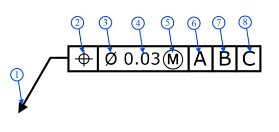
- Guide arrow: used to indicate the feature that needs to be controlled.
- Feature Control Symbol: used to express the category to be controlled, which is the position feature in the picture.
- Diameter symbol: When the controlled tolerance zone is circular, the diameter symbol should be included. Otherwise, it is not necessary.
- Geometric tolerance zone value: This means the value of the controlled tolerance zone is 0.03mm.
- Maximum material condition symbol: applicable only when the controlled feature is a slot or hole. If the datum is a plane, the maximum material condition symbol will not be used.
- First datum A: the primary reference point or plane selected on the part that serves as the initial basis for dimensional measurements and tolerances.
- Second datum B: Another reference point or plane on the part, along with Datum A establishes a coordinate system plane.
- Third datum C: The third reference point or plane to create a complete coordinate system.
BENEFITS OF GD&T IN PRACTICE
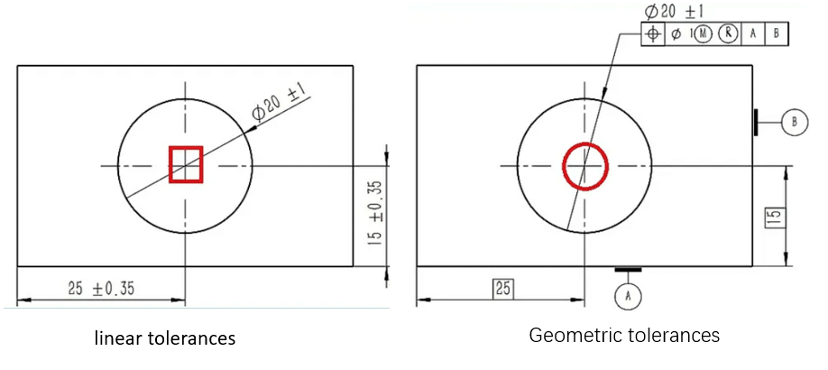
When we talk about the benefits of GD&T, it is always in comparison to linear dimensional tolerances. Here, let us explore what this means and exactly what the benefits of GD&T are.
Linear Dimensional Tolerances, also called linear tolerances, define the allowable range of dimensions for linear features such as lengths, widths, heights, and depths on a part. These tolerances indicate the acceptable limits within which the actual dimensions of a feature still keep the functionality of the part.
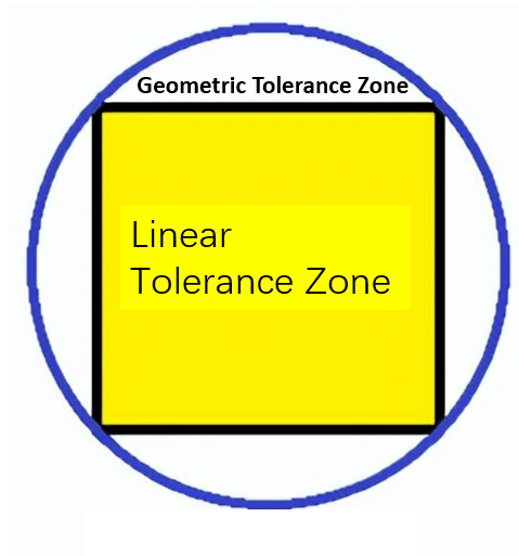
Geometric Tolerances Have a Wider Tolerance Zone.
As shown in the picture below, the linear dimensional tolerance annotates the axis line in the hole compared to the axis line annotated by the geometric tolerance in the hole.
More Clear Controlled Feature by Geometric Tolerance
Geometric tolerances have datums, which can indicate the controlled feature. Linear dimensions specify the size tolerance between two features, but geometric tolerances can define datums, accurately stating the tolerance of a specific feature. Below is a table summarizing where linear tolerances and geometric tolerances are used. From this table, you can see that geometric tolerances can control features that linear tolerances are not capable of.
| Tolerance Type | Linear Tolerance | Geometric Tolerance |
|---|---|---|
| Dimension | Better | |
| Chamfer | Better | |
| Radius | Better | |
| Wall Thickness | Better | |
| Step Face | Better | |
| Position Control | Better | |
| Orientation Control | Better | |
| Shape Control | Better |
COMMON GD&T SYMBOLS
GD&T is a feature-based system for defining the size, shape, and location of features on parts, each feature has one symbol and can be classified by categories. The commonly used categories are form, profile, orientation, location, and runout. Here We explain the definitions of the common GD&T symbol one by one as below:
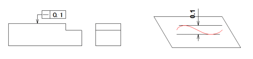
Straightness 
Straightness means the degree of straightness of linear elements on a component, reflecting the quality of not bending or curving not sloping to either side.
Example: Within a specified plane, the tolerance zone of Straightness must lie between two parallel lines separated by a distance of 0.1mm.
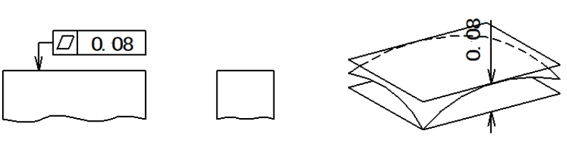
Flatness 
Flatness, sometimes called evenness, means the degree of flatness of planar elements on a component, reflecting the quality of being level and without curved.
Example: Within a specified area, the tolerance zone of flatness must lie between two parallel planes separated by a distance of 0.08mm.
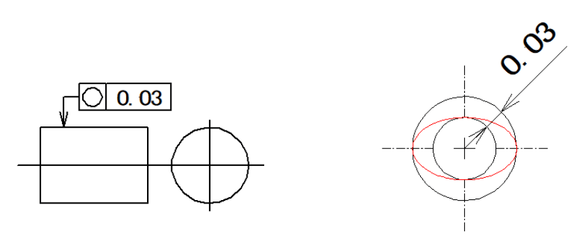
Circularity 
Circularity, also called roundness, means the degree of circularity of circular elements on a part, it is used to describe how close an object should be to an actual circle.
Example: The actual circle size must lie between two concentric circles with a radius difference of the tolerance value of 0.03mm.
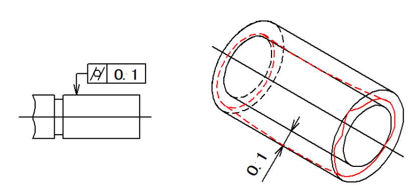
Cylindricity 
Cylindricity specifies the roundness and straightness of a cylinder.
Example: the tolerance zone of Cylindricity must lie between two coaxial cylindrical surfaces with a radius difference of the tolerance value of 0.1mm.
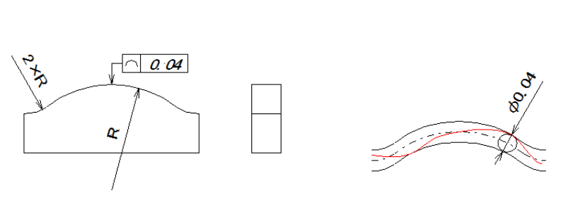
Line profile 
Line profile describes a tolerance zone to which any curve on a given plane of a component maintains its ideal shape.
Example: the tolerance zone is defined between the two envelope lines of a series of circles with diameters differing by the tolerance value of 0.04mm. The centers of these circles lie on a line with the theoretically correct geometric shape.
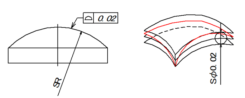
Surface profile 
Surface profile tolerance describes a three-dimensional tolerance zone around a surface, usually which is an advanced curve or shape.
Example: The tolerance zone is defined between the two-envelope plane of a series of spheres with diameters differing by 0.02mm. The centers of these spheres should theoretically lie on a surface with the correct geometric shape.
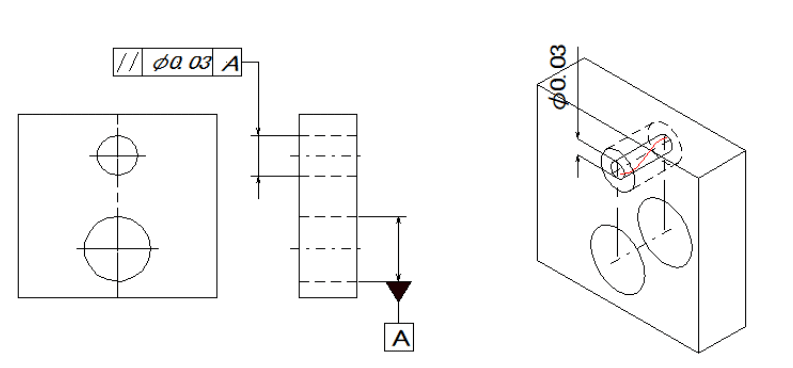
Parallelism

Parallelism is an orientation tolerance that maintains that two features (faces or axes) are parallel to each other.
Example: If the symbol φ is added before the tolerance value, then the tolerance zone lies within the cylindrical surface of a parallel diameter φ0.03mm to the reference.
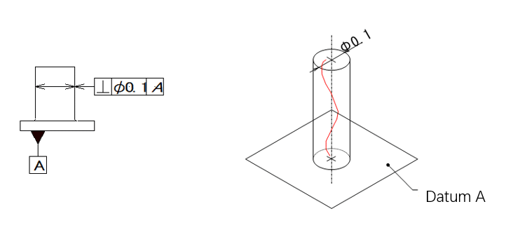
Perpendicularity 

Perpendicularity is a specific form of Angularity at 90°between two features.
Example: If the symbol φ is added before the tolerance value, then the tolerance zone lies within the cylindrical surface of a diameter φ0.1mm perpendicular to the reference plane.
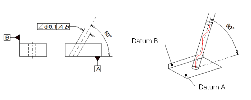
Angularity 
Angularity is a measure of maintaining any specified angle between two features on a component.
Example: If the symbol φ is added before the tolerance value, then the tolerance zone must lie within the cylindrical surface of a diameter of 0.1mm. This tolerance zone should be parallel to plane B, which is perpendicular to reference A, and should form an ideal angle of 60° with reference A.
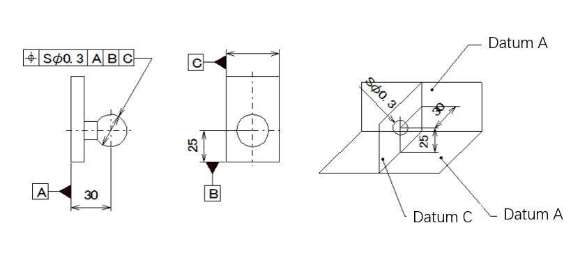
Position 
Position is used to control the accurate condition of elements such as points, lines, and surfaces on a component relative to their ideal positions.
Example: When the symbol Sφ is added before the tolerance value, the tolerance zone is the area within the sphere of diameter 0.3mm. The center point of the sphere’s tolerance zone is positioned relative to references A, B, and C according to their theoretical correct dimensions.
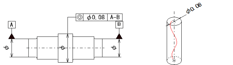
Concentricity 
Concentricity controls the condition of the measured axis on a component being in the same straight line relative to the datum axis.
Example: the tolerance zone is the area between two cylinders of diameter 0.08mm. The axis of the cylindrical tolerance zone coincides with the datum.
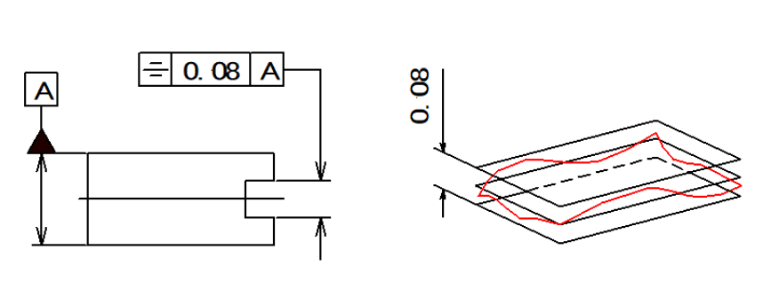
Symmetry 
Symmetry is a tolerance used to ensure that two symmetric features on a part are uniform across a datum plane.
Example: The tolerance zone is the area between two parallel planes or lines that are at a distance of 0.08mm from each other and symmetrically arranged relative to the datum center plane or centerline.
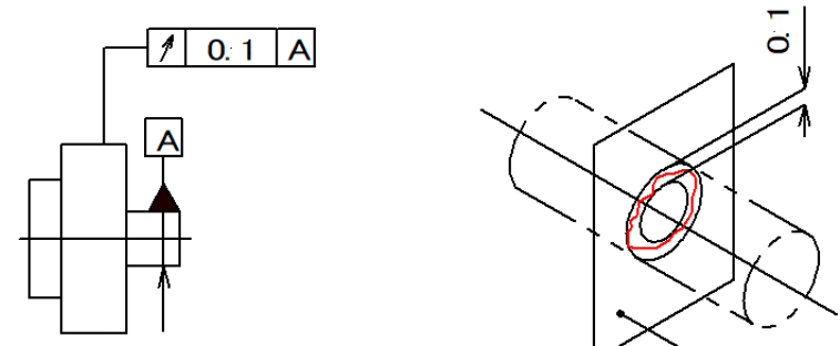
Circular runout 
Circular runout represents the condition where the rotating surface of a component, within a defined measurement plane, maintains a fixed position relative to the datum axis.
Example: The tolerance zone is the area between two concentric circles with a radius difference of 0.1mm, and both circles have their centers located on the same datum axis. The tolerance zone is perpendicular to any measurement plane.
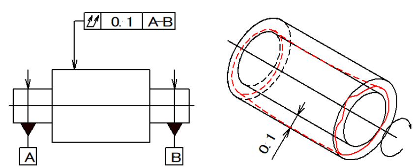
Total runout 
Total runout refers to the amount of runout along the entire measured surface of a component as it undergoes continuous rotation around the datum axis. it is a composite tolerance that controls the location, orientation, and cylindricity of the entire surface simultaneously.
Example: The tolerance zone is the area between two coaxial cylindrical surfaces with a radius difference of 0.1mm and aligned with the datum axis.
GD&T SYMBOLS CHART
To make it easier to check and fully understand the common GD&T symbols, we have collected all the critical information into the chart for the best reference. This chart will help you quickly and accurately identify the symbols, making your GD&T work more efficient and convenient.
| Tolerance type | Geometric Characteristic | Symbol | ASME Section | Feature Modifier needs | Datums needs |
| Form | Straightness | 6.4.1 | YES | No | |
| Flatness | | 6.4.2 | No | ||
| Circularity | 6.4.3 | No | |||
| Cylindricity | 6.4.4 | No | |||
| Profile | Line profile | 6.5.2(b) | No | Sometimes | |
| Surface profile | 6.5.2(a) | No | |||
| Orientation | Parallelism |  | 6.6.3 | YES | YES |
| Perpendicularity |  | 6.6.4 | YES | ||
| Angularity | 6.6.2 | YES | |||
| Location | Position | 5.2 | YES | ||
| Concentricity | 5.11.3 | NO | |||
| Symmetry | 5.13 | NO | |||
| Runout | Circular runout | 6.7.1.2.1 | NO | ||
| Total runout | 6.7.1.2.2 | NO |
COMMON MODIFIER SYMBOLS CHART
Modifier symbols in GD&T are important because they provide additional information that modifies the tolerance or feature control. These modifiers help define the specific conditions under which a feature is toleranced, allowing for greater precision and clarity in design and manufacturing. To make it easier to understand, we’ve created a chart for the common modifier symbols, explaining what each symbol means.
| Symbol | Modifier | description |
 | Continuous Feature | This symbol is used to identify a group of features |
 | Statistical Tolerance | This symbol means the feature should be produced with Statistical Process Control (SPC). |
 | Envelope | This symbol means the feature has to fit inside. |
 | Free State | This applies only when part is restrained. |
 | Independence | no limits to the number of errors |
 | Least Material Condition | use to keep minimum wall thickness. |
 | Maximum Material Condition | Provides additional tolerance for a feature of size. |
 | Projected Tolerance Zone | Used on threaded holes for long studs. |
 | Tangent Plane | Used for interfaces where the form is not required. |
GEOMETRIC TOLERANCE STANDARDS OF VARIOUS COUNTRIES
Geometric tolerance standards come from international guidelines that define the rules for specifying and interpreting geometric tolerances. Although most of the content in GD&T standards is the same across different countries, some countries have their own standard versions, as listed below:
American Standard: ASME Y14.5—2018 Dimensioning and Tolerancing
Y14.5 is the most authoritative standard that establishes principles, definitions, requirements, defaults, tolerances, and related specifications in engineering drawings and associated documents. you can buy ASME Y14.5 from the ASME website.
International standard: ISO 1101-2017
Chinese standard: GB/T 1182-2008 (equivalent to ISO1101)
German standard: DIN ISO 1101 (equivalent to ISO1101)
Japanese Standard: JIS B0021 (equivalent to ISO1101)
British Standard: BS ISO 1101 (equivalent to ISO1101)
Conclusion
GD&T offers an effective method to express design dimensions and tolerances. At KUSLA, our engineer has rich experience in how to measure these Geometric dimensions and provide full-dimension inspection reports to guarantee the quality of your machined products. Contact us and request an instant quote today for your projects.
FAQs About GD&T Symbols
How to measure GD&T Symbols?
Measure different GD&T symbols needs different measuring Instruments and gauges, for example, Using a dial indicator holder, a lever-type dial gauge can be attached to measure parallelism, flatness, and straightness.
Is Concentricity obsolete?
Yes, the use of concentricity has been eliminated under the 2018 ASME Y 14.5 GD&T Standard, because other characteristics provide more direct control of features and establish requirements that have a well-defined meaning.
What is the main difference between flatness and straightness?
Flatness is a property of a plane, while straightness is about a straight line that only has length.